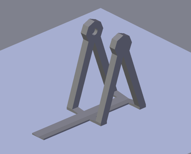
Now that the frame is complete and ready to print, as seen in Part 2, it’s time to do the moving parts. This is a very good place to show you the Blender 3D Cursor in operation, because I will not be designing with exact dimensions, but rather with exact locations and approximate dimensions.
The 3D cursor is the thing that moves around the screen, when you click the left mouse button. You can place it with nice precision, when you use the views that are flat, ie. Top, Left, or Right, because then the cursor moves in only two dimensions. Placing the cursor in the User Perspective view is really hard, unless you snap the cursor onto something – most of the time it is not even possible. I’ll show you what I mean.
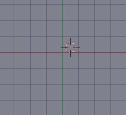
This image shows you the cursor near the center of the scene (you can see the red X axis and the green Y axis there):
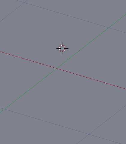
When you now press down the mouse wheel and move the mouse, ie. enter the User Perspective view, you can see the cursor is not where you thought it to be. It is above the scene:
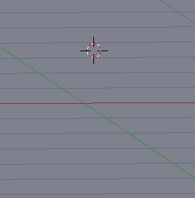
You can see it even more clearly, if you move the viewpoint almost to the scene plane:
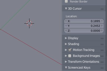
Luckily Blender has the information you need for the 3D cursor in the Properties panel on the right of the scene:
This tells you that the cursor is now slightly off the center both in the X and Y directions, but is flat on the Z axis. If you use the spinners in the Location box, you can place the cursor in any point in space, and since all new objects appear in the location of the 3D cursor, this is a very handy thing.
But it is not nearly as handy as the Snapping tool. With that, you can select any element in the scene, be it a vertex, edge, face, mesh, or group of meshes, and then press Shift+S, you get the Snap menu. I will return to the trebuchet project to illustrate the use of the Snap menu now.
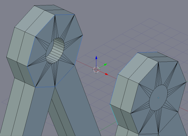
To get the main axle done, I will select the hexagonal edge loops at the top of the frame, on both sides. This will place the pivot point in the exact center of the distance between the edge loops, and that location is very good for placing a cylinder that will become the main axle.
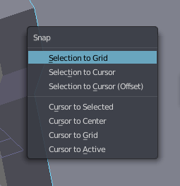
Now that you see the three-axis arrowheaded pointy thingie, actually called the 3D manipulator widget, lies between the selected loops, you can press Shift+S. You then get this menu:
When you now pick Cursor to Selected, you get the cursor exactly where you want it. You can also snap the cursor to the center of the scene, to the nearest grid intersection, or to the origin point of the active element. The upper menu is used to move the selected object (again, any vertex, edge, face, or entire mesh) to the Grid or to the 3D cursor. Using the snap menu twice will enable you first to place the cursor where you want the object, and then snap the object to the cursor, and once you understand how it works, you meshes will always look tidy.
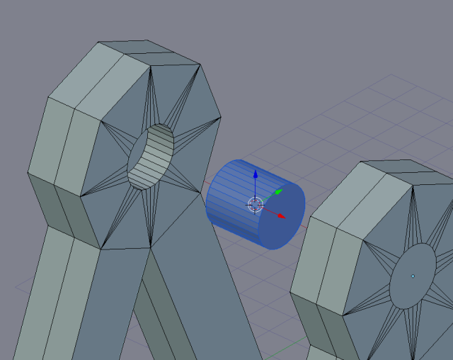
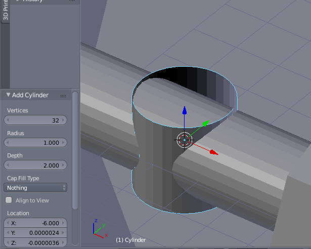
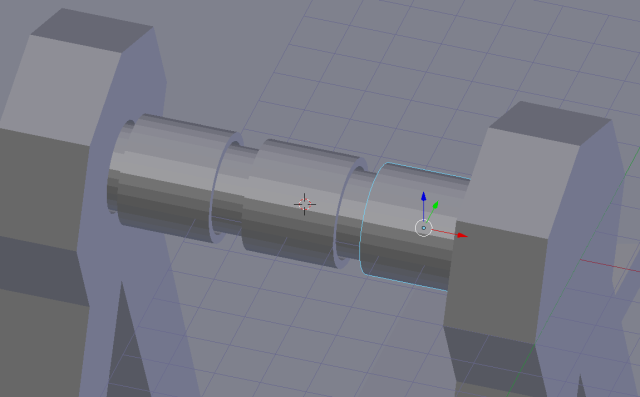
To get the axle placed now, all I need to do is select Shift+A and then Cylinder. This will place a cylinder in the right place (remember, all objects are created in the location of the cursor, and with the origin point in the center of the object). I can then adjust the number of vertices I want the axle to have and rotate it along the Y axis to get it in the right attitude:
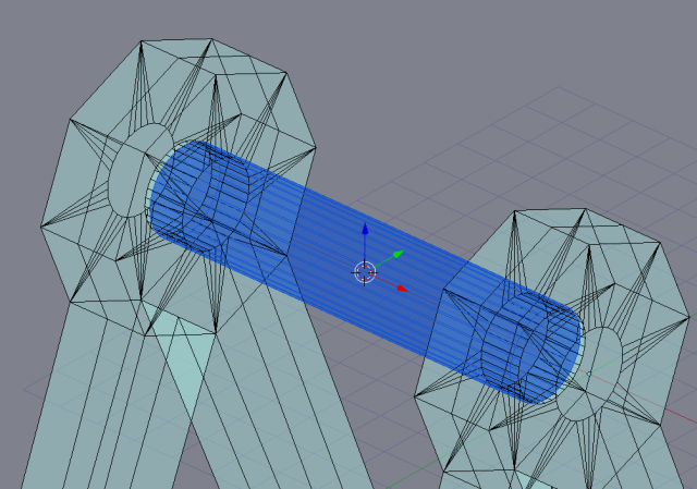
Now that I am building this to be printed, I don’t need exact fit. I can just scale the axle along the X axis to make it long enough, and then scale it down along the Y and Z axes to make it small enough to fit the frame.
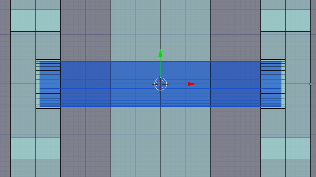
Sometimes it is a good idea to use the see-thru settings, bu many times it is really hard to understand what is what. In this case, however, seeing through the frame works well, especially if you look at the system from thet Top view:
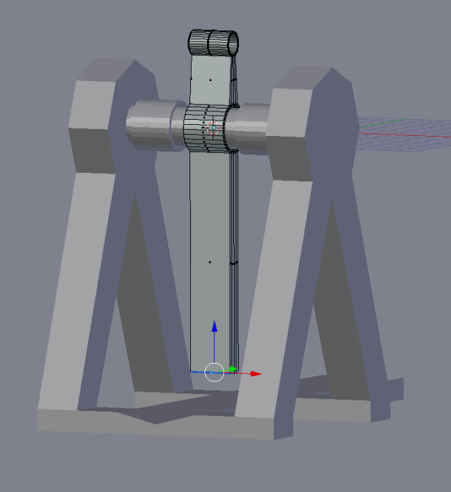
This will print nicely. The next thing to do is to create the swing arm, which is actually a nice exercise in extrusion. Because the 3D cursor is in the right place, in the center of the acle, it is now possible to create another cylinder, this time a little larger, in the same location.
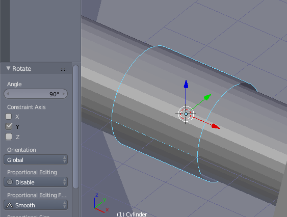
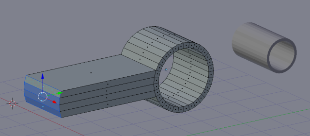
32 vertices will do nicely, because the printer resolution is low enough to make it fully round anyhow. There is no need for the cylinder to have ends, because it will be a set on the axle. Let’s just rotate it along the Y axis for 90 degrees, then select the ends, and extrude:
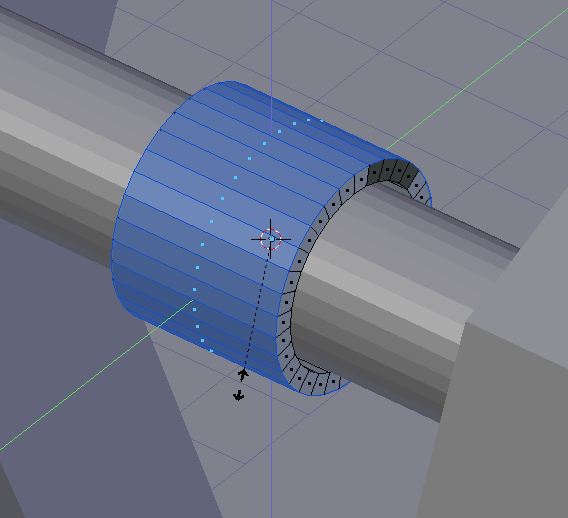
When you now enter Edit mode, you can extrude. Press E for Extrude, then S for Scale, and Shift-X to leave the X axis away from the scaling. Moving the mouse gives you a nice cylinder wall with whatever thickness you give it when you drag the mouse. End the operation with the Enter key.
The swing arm is in the middle of the axle. To keep it in place, we need two bushings around it. The easiest way is merely to duplicate this cylinder twice and move them along the X axis to the left and right of this cylinder.
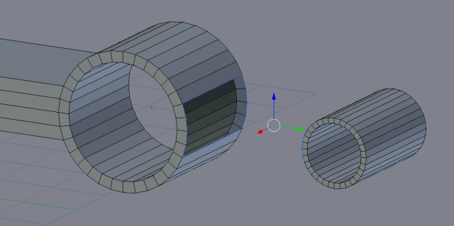
Their length along the axle can be adjusted later, but it is easiest to create them at this point. Now for the swing arm. Its length is defined by the height of the frame, but at this point we don’t need to think of dimensions – all we care for now is the shape. To create the swing arm we will extrude 4 of the 32 faces that make up the outer wall of the swing arm cylinder.
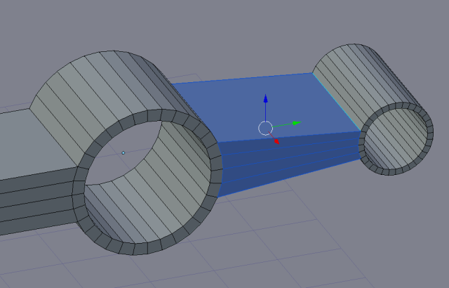
As you see, I have already created a smaller duplicate of the cylinder, because this is where the counterweight bucket will hang. I duplicated the cylinder before extruding, then scaled it along the Y and Z, but not X, and moved it away along the Y axis. It is important to stick to the axis here, because the balance of the arm has to stay on the longitudinal axis, ie. the Y here. The length of the two cylinders must be the same, otherwise the swing arm will need support structures when it is printed. To join the two cylinders, the easiest way is to remove four faces that are facing each other, and then bridge the gap:
You can either select edges one by one, or, you can use the Bridge button in the LoopTools addon. LoopTools is one of the most vitally important addons to Blender. All you need to do is to select the edges of the holes you want to bridge, then select Bridge from LoopTools, and it will form faces between the edges.
The length of the swing arm can be adjusted by grabbing the faces at the end of the swing arm and pulling down until you have it long enough. This, as all other dragging motions, is best done by first rotating the arm until vertical, and then dragging along the Z axis. Never do anything like this in the User Perspective, as you can’t get it done straight.
The operation of the swing arm assumes that you have the sling tied to the swing arm at one end, and there’s a loose end with a ring or something stuck into a pin. When the sling passes the end of the swing arm, the ring will slip free from the pin and release the payload. I haven’t yet made it all work, but I have used a piece of filament as the pin, and tied a test sling to it. It may work, and you’re free to try whatever you wish.
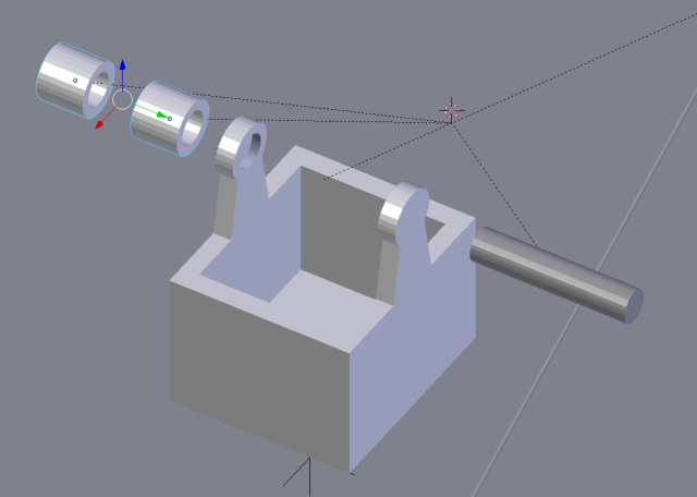
Then we think of the counterweight bucket. It is really easy to do, and I will leave it as an exercise for you to design. All you have to do is to insert a plane between the legs of the frame to measure the max width of the bucket, then extrude up to form the bottom, then add a couple of edge loops to get extrudable sides. This image shows you the bucket:
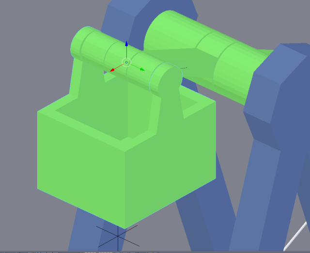
The axle mountings are done exactly like they were done on the frame. Use the hole on the swing arm to give you the diameter of the axle, and then use it for the axle mounting holes too. The bushings are also designed just as in the main axle. This image shows the mounted counterweight bucket:
This essentially concludes the building of the trebuchet in Blender. All that remains is to arrange the parts on the grid for printing. At this point I will remind you that a 3D printer assumes all parts are flat and level, but it is easy to have parts that are just a little off the grid. This will result in unprintable configurations. I have sometimes wondered why a print would not stick to the table, and the reason was that the mesh was one millimeter or so off the table in the STL file, and the printer tries to print it anyway.
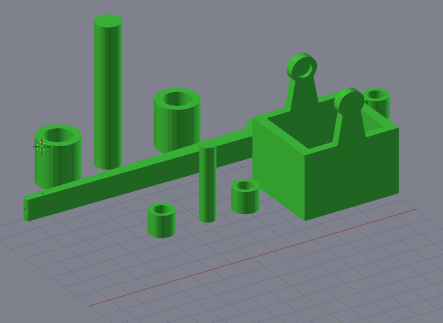
Again, in this phase, the 3D cursor is your best friend. For every piece you want to print, use the 3D printer to bring the origin of the item to the lowest face of the mesh, then snap the mesh to the grid. This way you will have all items with the lowest face exactly level with all of the other parts, as well as the grid. Then you can move the pieces to a nice constellation on the table, as in this picture:
So you can print all moving parts at one go, and the frame in another session. The frame will take 5.5 hours, with a layer thickness of 0.3mm and a 30% infill. The moving parts are a 2-2.5 hour print job.
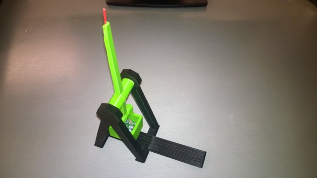
Mounting the moving parts is easy – merely push the axles into the swing arm, add the bushings, and then push the axles in the frame and the bucket with a mild bending effort. If you have measured the axle length properly, they will just snap into place. This is the final, assembled trebuchet without the sling:
If you don’t want to design your own, you can get my design from Thingiverse. Happy Blendering!

